- 您现在的位置:买卖IC网 > Sheet目录221 > DS1217M-L04 (Maxim Integrated)RAM READ/WRITE NV LO LEAK 4MEG
�� �
�
 �
�DS1217M� Nonvolatile� Read/Write� Cartridge�
�inputs� A8� through� A11)� must� be� executed� to� guarantee� that� pattern� entry� starts� with� the� first� set� of� 3� bits.� Each� set�
�of� address� inputs� is� entered� into� the� DS1217M� by� executing� read� cycles.� The� first� 11� cycles� must� match� the� exact�
�bit� pattern� as� shown� in� Table� 2.� The� last� five� cycles� must� match� the� exact� bit� pattern� for� addresses� A9,� A10,� and�
�A11.� However,� address� line� 8� defines� which� of� the� 16� banks� is� to� be� enabled,� or� all� banks� are� deselected,� as� per�
�Table� 3.� Switching� from� one� bank� to� another� occurs� as� the� last� of� the� 16� read� cycles� is� completed.� A� single� bank� is�
�selected� at� any� one� time.� A� selected� bank� will� remain� active� until� a� new� bank� is� selected,� all� banks� are� deselected,�
�or� until� power� is� lost.� (See� the� DS1222� BankSwitch� Chip� data� sheet� for� more� detail.)�
�Remote� Connection� through� a� Ribbon� Cable�
�Existing� systems� that� contain� 28-pin� bytewide� sockets� can� be� retrofitted� using� a� 28-pin� DIP� plug.� The� DIP� plug,�
�AMP� Part� Number� 746616-2,� can� be� inserted� into� the� 28-pin� site� after� the� memory� is� removed.� Connection� to� the�
�cartridge� is� accomplished� via� a� 28-pin� cable� connected� to� a� 30-contact� card� edge� connector,� AMP� Part� Number�
�499188-4.� The� 28-pin� ribbon� cable� must� be� right� justified,� such� that� positions� A1� and� B1� are� left� disconnected.� For�
�applications� where� the� cartridge� is� installed� or� removed� with� power� applied,� both� ground� contacts� (A1� and� B1)� on�
�the� card� edge� connector� should� be� grounded� to� further� enhance� data� integrity.� Access� time� push-out� may� occur� as�
�the� distance� between� the� cartridge� and� the� driving� circuitry� is� increased.�
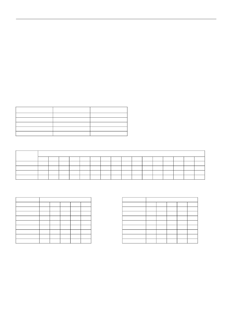
�Table� 1.� Cartridge� Numbering�
�PART�
�DS1217M� 1/2-25�
�DS1217M� 1-25�
�DS1217M� 2-25�
�DS1217M� 3-25�
�DS1217M� 4-25�
�DENSITY�
�64kB� x� 8�
�128kB� x� 8�
�256kB� x� 8�
�384kB� x� 8�
�512kB� x� 8�
�NO.� OF� BANKS�
�2�
�4�
�8�
�12�
�16�
�Table� 2.� Address� Input� Pattern�
�ADDRESS�
�BIT� SEQUENCE�
�INPUTS�
�A8�
�A9�
�A10�
�A11�
�0�
�1�
�0�
�1�
�0�
�1�
�0�
�1�
�0�
�1�
�2�
�1�
�0�
�1�
�0�
�3�
�0�
�1�
�0�
�1�
�4�
�0�
�1�
�0�
�1�
�5�
�0�
�1�
�0�
�1�
�6�
�1�
�0�
�1�
�0�
�7�
�1�
�0�
�1�
�0�
�8�
�0�
�1�
�0�
�1�
�9�
�1�
�0�
�1�
�0�
�10�
�0�
�1�
�0�
�1�
�11�
�X�
�0�
�1�
�0�
�12�
�X�
�0�
�1�
�0�
�13�
�X�
�0�
�1�
�0�
�14�
�X�
�1�
�0�
�1�
�15�
�X�
�1�
�0�
�1�
�X� =� See� Table� 3�
�Table� 3.� Bank� Select� Table�
�BANK�
�A8� BIT� SEQUENCE�
�BANK�
�A8� BIT� SEQUENCE�
�SELECTED�
�BANKS� OFF�
�BANK� 0�
�BANK� 1�
�BANK� 2�
�BANK� 3�
�BANK� 4�
�BANK� 5�
�BANK� 6�
�11�
�0�
�X�
�1�
�1�
�1�
�1�
�1�
�1�
�12�
�X�
�0�
�0�
�0�
�0�
�0�
�0�
�0�
�13�
�X�
�0�
�0�
�0�
�0�
�1�
�1�
�1�
�14�
�X�
�0�
�0�
�1�
�1�
�0�
�0�
�1�
�15�
�X�
�0�
�1�
�0�
�1�
�0�
�1�
�0�
�BANK� 7�
�BANK� 8�
�BANK� 9�
�BANK� 10�
�BANK� 11�
�BANK� 12�
�BANK� 13�
�BANK� 14�
�BANK� 15�
�1�
�1�
�1�
�1�
�1�
�1�
�1�
�1�
�1�
�0�
�1�
�1�
�1�
�1�
�1�
�1�
�1�
�1�
�1�
�0�
�0�
�0�
�0�
�1�
�1�
�1�
�1�
�1�
�0�
�0�
�1�
�1�
�0�
�0�
�1�
�1�
�1�
�0�
�1�
�0�
�1�
�0�
�1�
�0�
�1�
�7� of� 8�
�发布紧急采购,3分钟左右您将得到回复。
相关PDF资料
DS1904L-F5#
IBUTTON RTC F5 MICROCAN
DS1920-F5+
IBUTTON TEMPERATURE F5
DS1921G-F5#
IBUTTON THERMOCHRON F5
DS1921H-F5#
IBUTTON THERMOCHRON F5
DS1921K#
KIT IBUTTON THERMOCHRON
DS1922E-F5#
IBUTTON TEMP LOGGER 4KBit F5
DS1922L-F5#
IBUTTON TEMP LOGGER
DS1923-F5#
IBUTTON TEMP/HUMIDITY LOGGER F5
相关代理商/技术参数
DS-1217ZJ
制造商:Hikvision USA 功能描述:Dome Camera Pendant Mount9.06In X 7.09In X 6.30 制造商:HIKVISION 功能描述:DOME CAMERA PENDANT MOUNT 9.06IN X 7.09IN X 6.30
DS1218
功能描述:IC CONTROLLER NV 8-DIP RoHS:否 类别:集成电路 (IC) >> 存储器 - 控制器 系列:- 标准包装:45 系列:- 控制器类型:静态 RAM(SRAM) 电源电压:4.5 V ~ 5.5 V 工作温度:0°C ~ 70°C 封装/外壳:16-SOIC(0.295",7.50mm 宽) 供应商设备封装:16-SOIC W 包装:管件
DS1218+
功能描述:存储器控制器 Nonvolatile Controller RoHS:否 制造商:Maxim Integrated
DS1218B2
制造商:Maxim Integrated Products 功能描述:1218B2
DS1218S
功能描述:IC CONTROLLER NV 8-SOIC RoHS:否 类别:集成电路 (IC) >> 存储器 - 控制器 系列:- 标准包装:45 系列:- 控制器类型:静态 RAM(SRAM) 电源电压:4.5 V ~ 5.5 V 工作温度:0°C ~ 70°C 封装/外壳:16-SOIC(0.295",7.50mm 宽) 供应商设备封装:16-SOIC W 包装:管件
DS1218S/T&R
制造商:Maxim Integrated Products 功能描述:CONTROLLER NV 8P SOIC T&R - Tape and Reel 制造商:Maxim Integrated Products 功能描述:IC CONTROLLER NV 8-SOIC
DS1218S/T&R
功能描述:IC CONTROLLER NV 8-SOIC RoHS:否 类别:集成电路 (IC) >> 存储器 - 控制器 系列:- 标准包装:45 系列:- 控制器类型:静态 RAM(SRAM) 电源电压:4.5 V ~ 5.5 V 工作温度:0°C ~ 70°C 封装/外壳:16-SOIC(0.295",7.50mm 宽) 供应商设备封装:16-SOIC W 包装:管件
DS1218S+
功能描述:存储器控制器 Nonvolatile Controller RoHS:否 制造商:Maxim Integrated